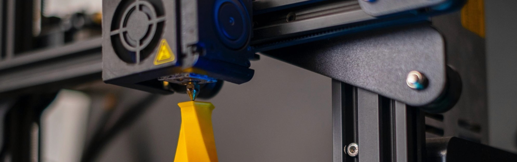
3D Printing
3D printing tips for FDM considering limitations and design requirements.
Sep 10, 2019
Whenever you are 3D printing, you need to consider two critical aspects that will determine the object's quality. The first one focuses on the 3D printer itself, including reliability, technical features, and material. The second one considers the design and its adaptation to the chosen manufacturing technology.
In this article, we will go through some of the most crucial design aspects you should consider when designing for FDM 3D printing (Fused Deposition Modelling). This will help you increase efficiency and make better products.
Tips for designing for 3D Printing
The following tips are based on FDM 3D printing limitations and design requirements. However, they are also helpful if you're prototyping with other 3D printing technologies such as SLA, DLP or SLS.
Wall thickness
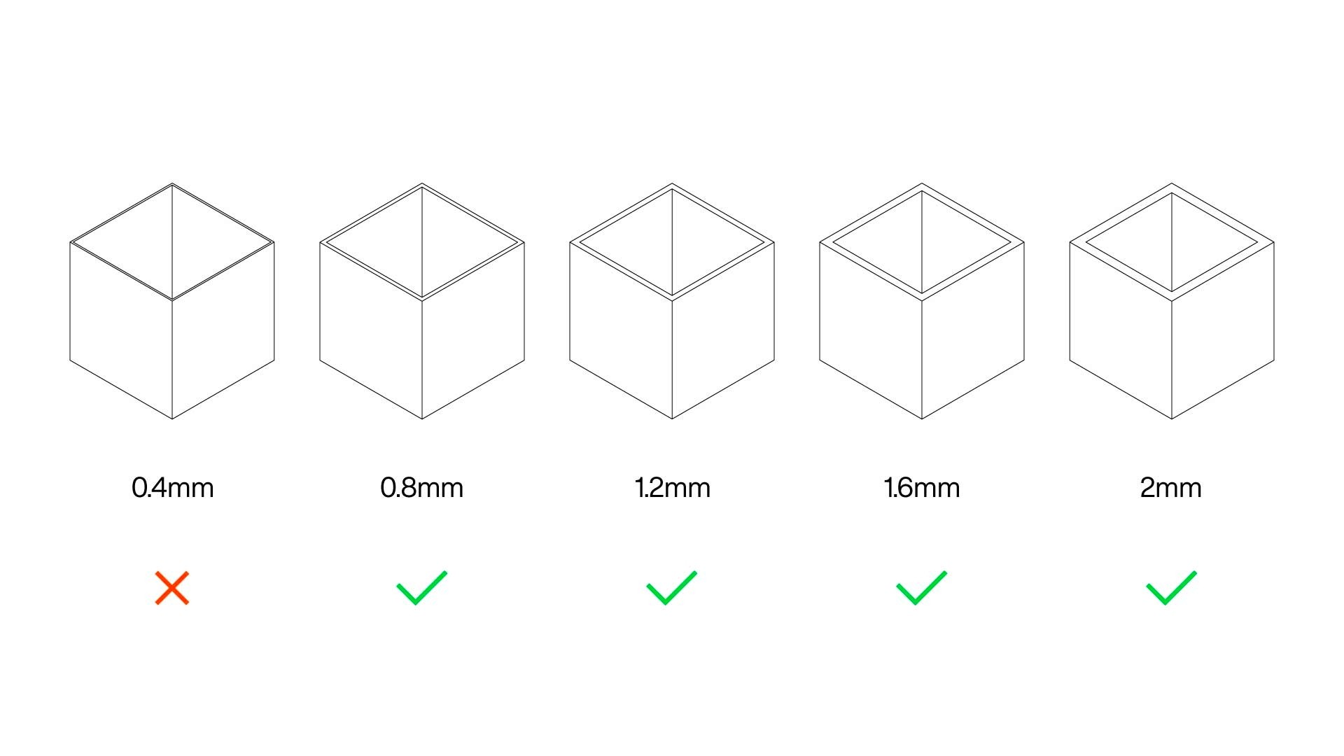
If you're designing an enclosure or the outer shell of a product, you need to consider that the minimum wall thickness for FDM 3D printing is 0.8mm. The wall thickness is highly related to the nozzle diameter, which is the element where the material is extruded.
The standard nozzle diameter is 0.4mm, and the wall thickness should be at least two times the nozzle diameter. If you use a 0.8mm nozzle, the wall thickness should then be at least 1.6mm.
Depending on the slicing software that you use, thinner walls may be ignored and not printed or they may be printed, although the surface quality and part strength will be reduced.
Bridges
Bridging refers to the ability of the 3D printer to print in the air between two points without the need for support material.
Even though bridging is heavily affected by the 3D printer and the materials that are used, it's not recommended to add gaps or bridges of over 15mm. If a design includes gaps larger than 15mm, the lower part of the bridge will sag unless support material is added. Reducing the gap size is the best solution, as using support material can slightly damage the surface where the support material touches the part.
It's important to mention that bridges connect two points that are at the same height, and it connects them with a straight line. Any gap that connects two points at different heights is an overhang.

Overhangs
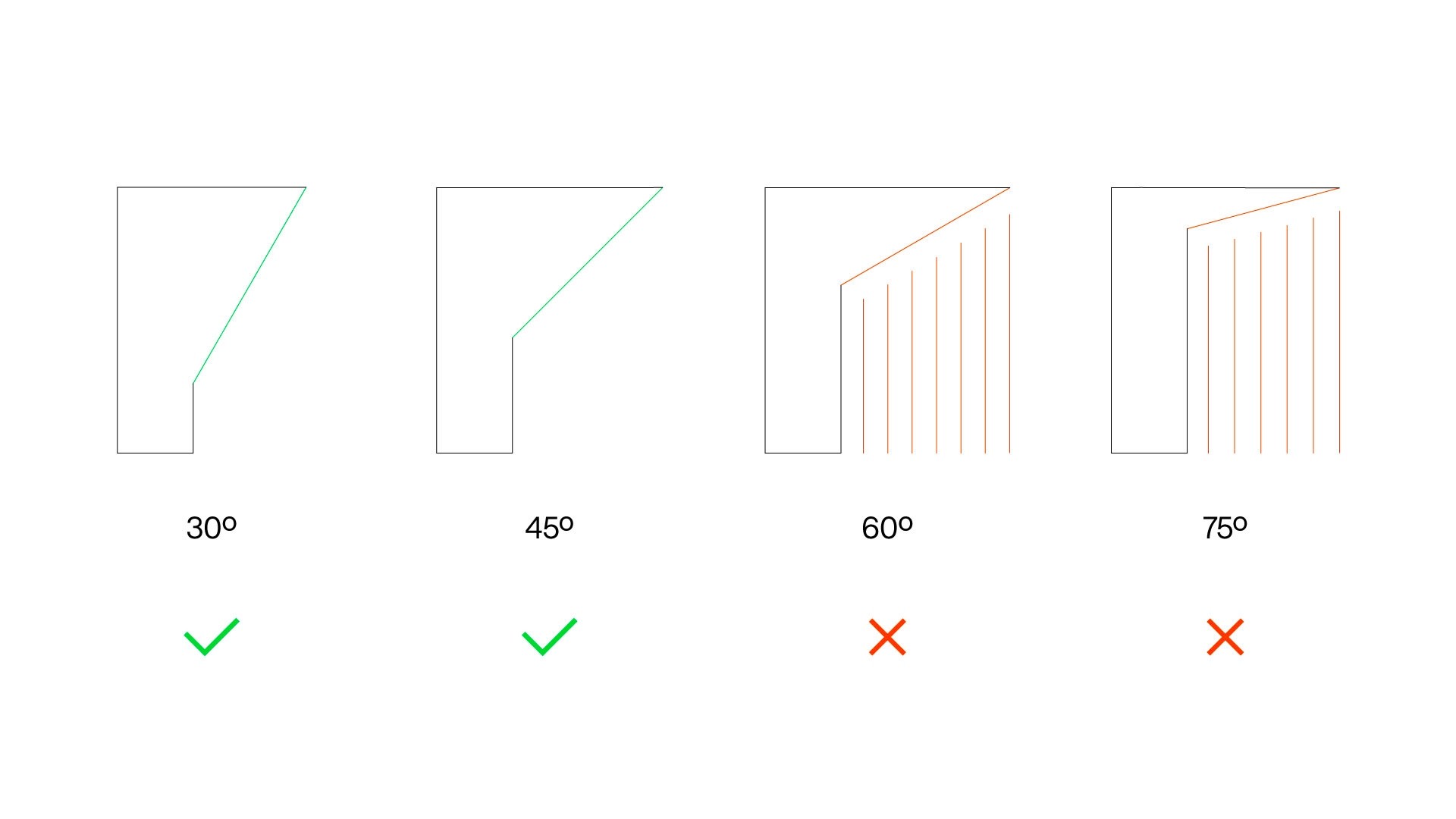
FDM 3D printers deposit multiple layers of plastic one on top of each other to create an object. You can't print in the air. This means that you either control the overhangs in your design or you use support material. Overhangs up to 45º print at high quality. Depending on the material, layer height and 3D printer you use, you may be able to print overhangs of up to 60º with decent quality. It's recommended to use support material on all overhangs above 60º.
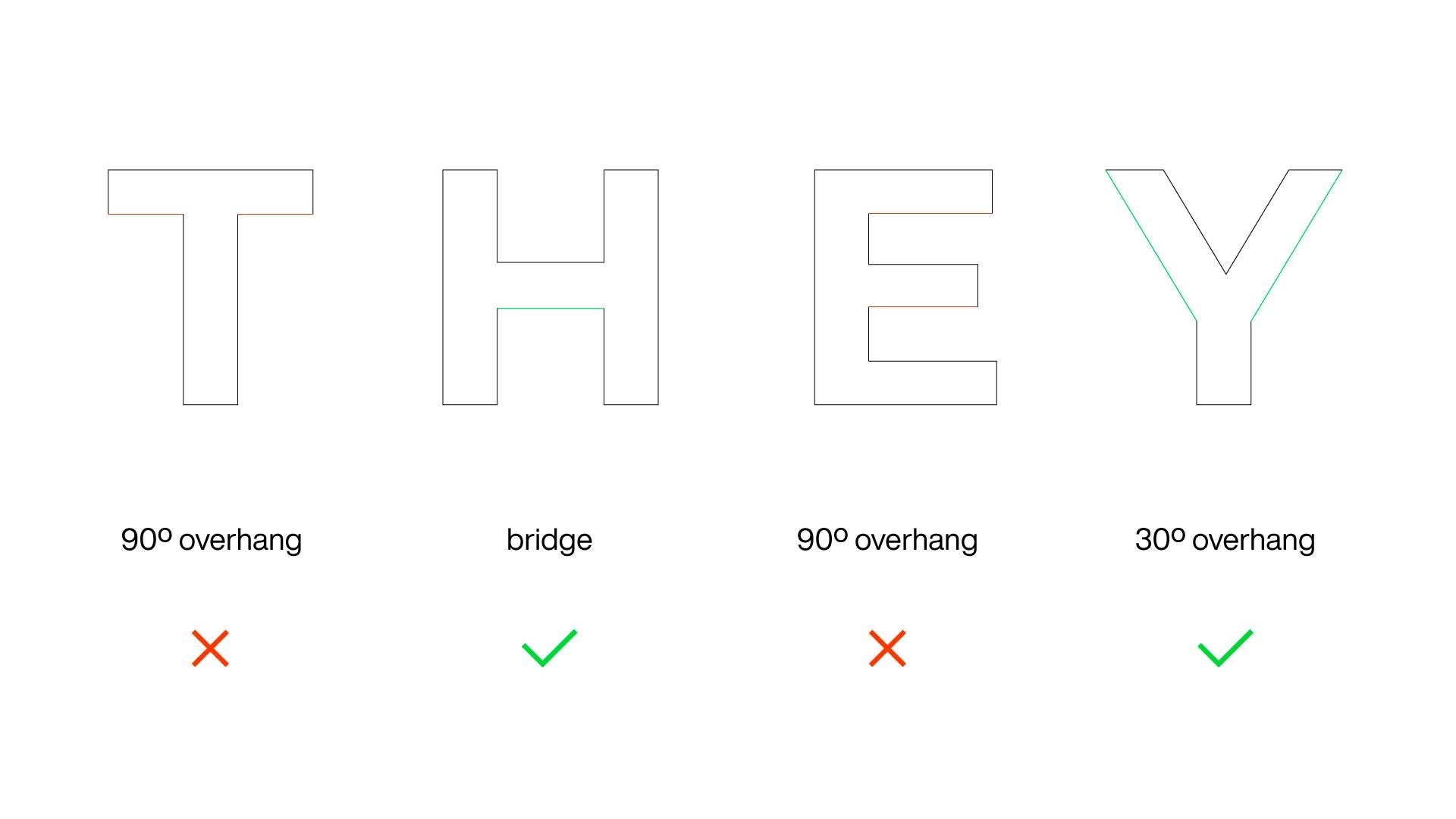
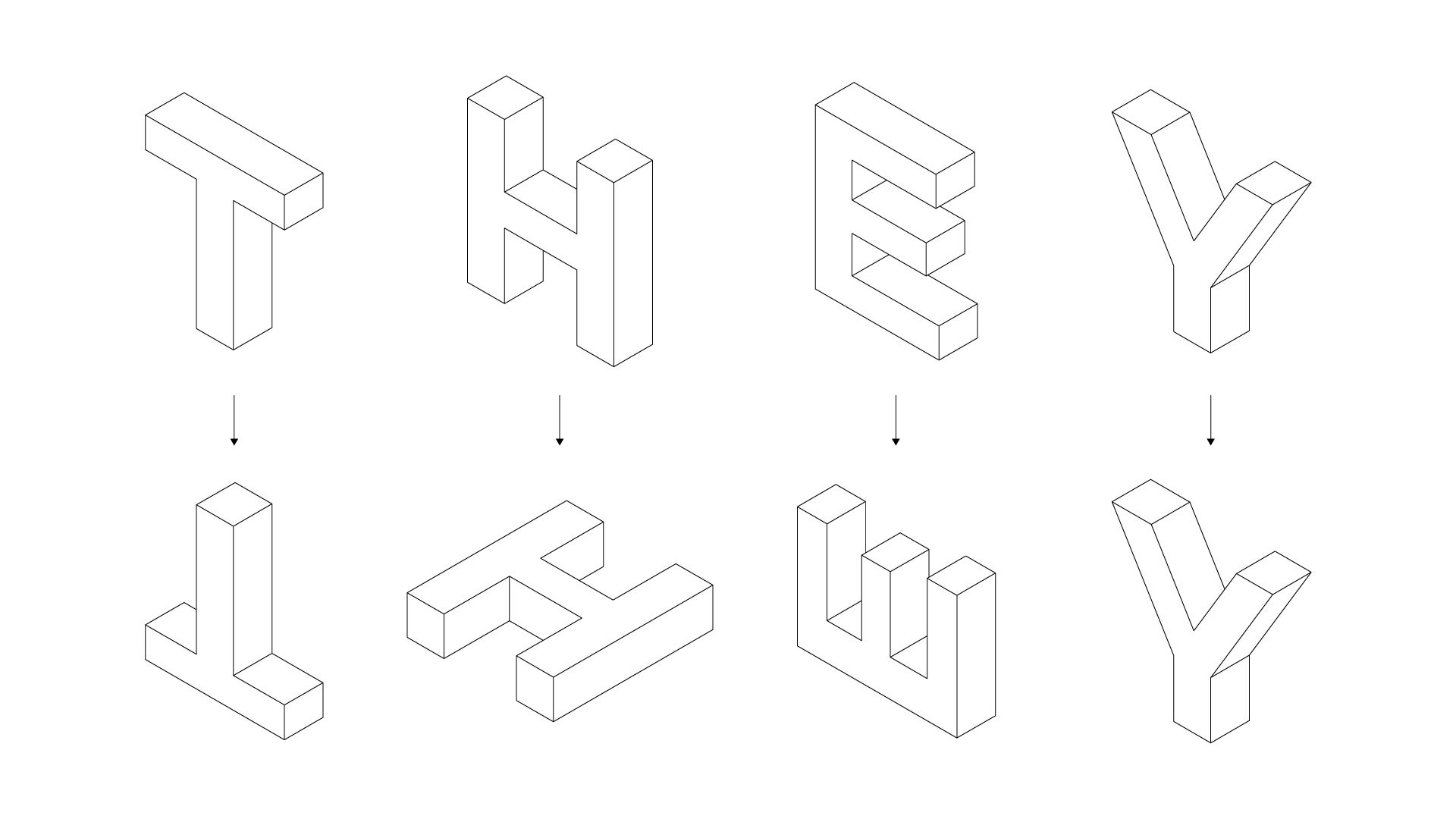
A great way to see the different type of overhangs and bridges is with the word THEY. Each one of the letters has a unique shape, and some of the most common 3D printing problems would show up if the letters were 3D printed in their original position. As you can see in the image below, both T and E have two overhangs, which would require support material. However, the letter H has a bridge and the letter Y has small overhangs, meaning that those two letters could be 3D printed in their original position.
Vertical holes
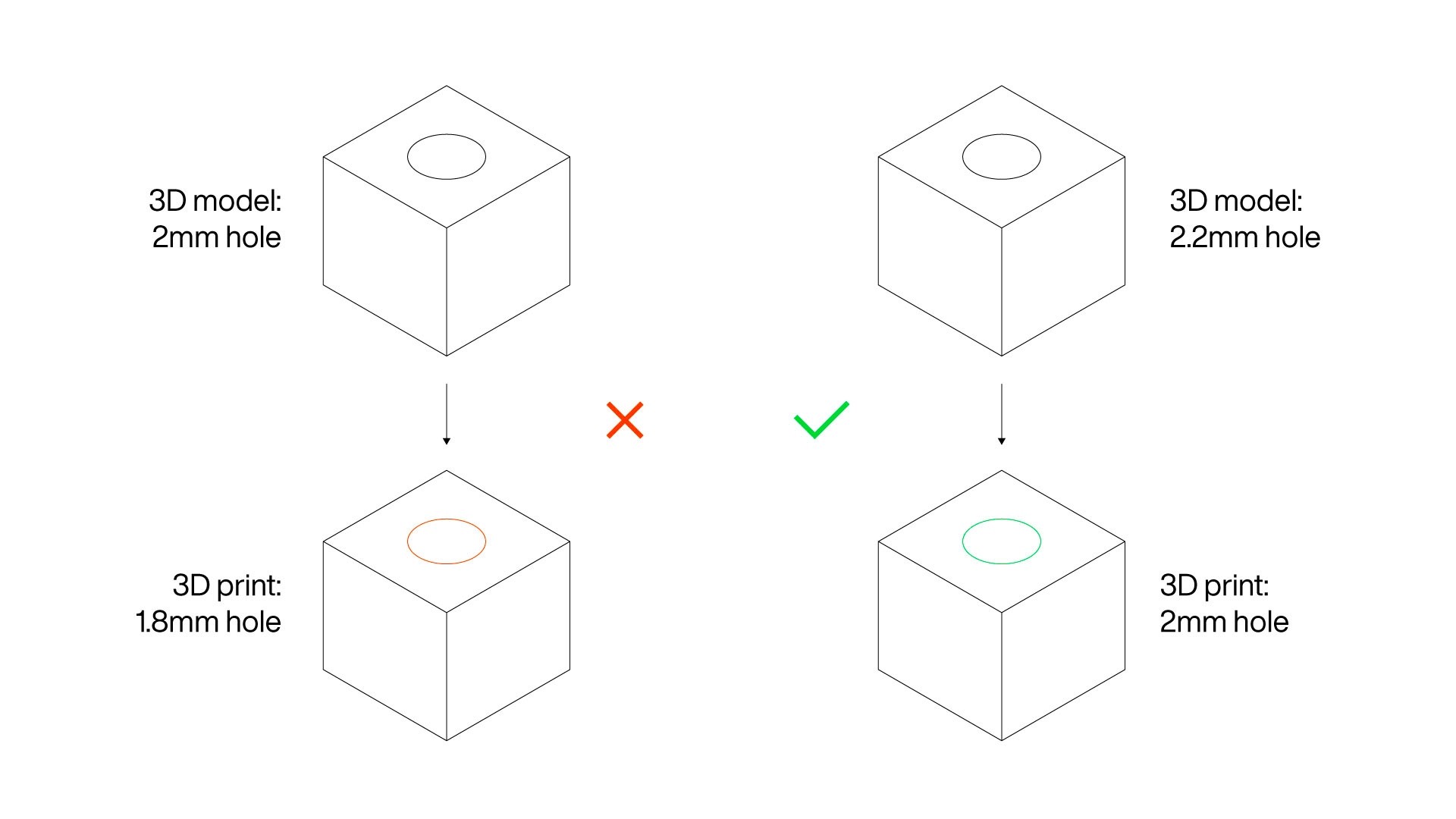
If you're used to FDM 3D printing, you will know that undersized vertical holes are a common issue. This is related to the manufacturing process, as the extruded plastic is compressed against the previous layer, expanding on the XY plane, making holes smaller than expected.
Vertical hole size variations are affected by the type of 3D printer, material and print settings. The best solution is to run some tests to find the amount of undersize and compensate it in the design. For example, if you want a 2mm hole, you may need to add 0.2mm to compensate it.
If making changes in the 3D model is not possible, the holes can be simply drilled after printing. This option takes time, but it offers the highest possible accuracy.
In those cases where fasteners are going to be inserted in vertical holes, you can undersize them on purpose to avoid using nuts. For example, if you're going to use 3mm screws, the holes can be 2.8mm, generating a tight grip when you insert them. Think that if the holes are too small, the part may break when you insert the fastener.
Horizontal holes and arches
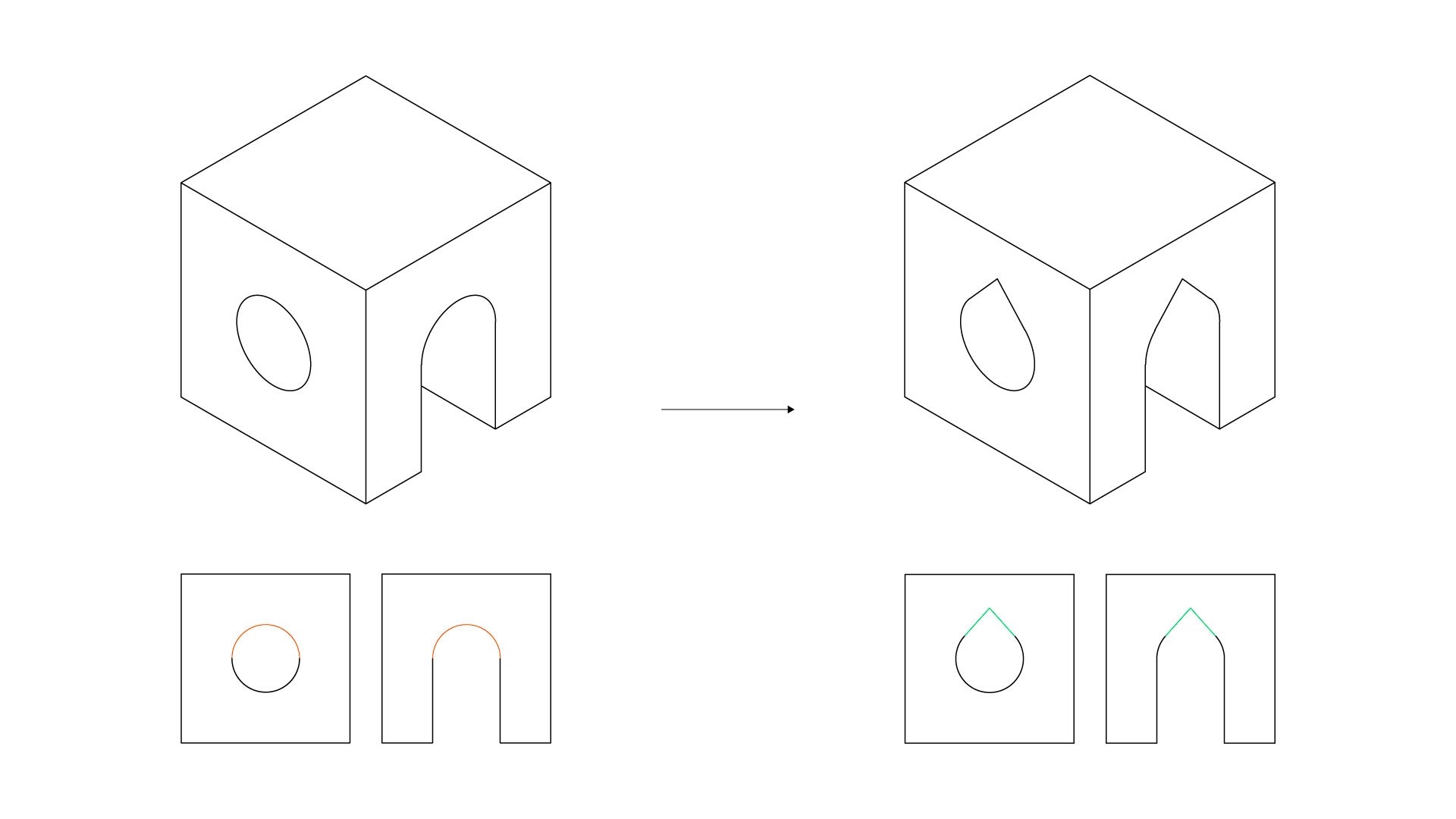
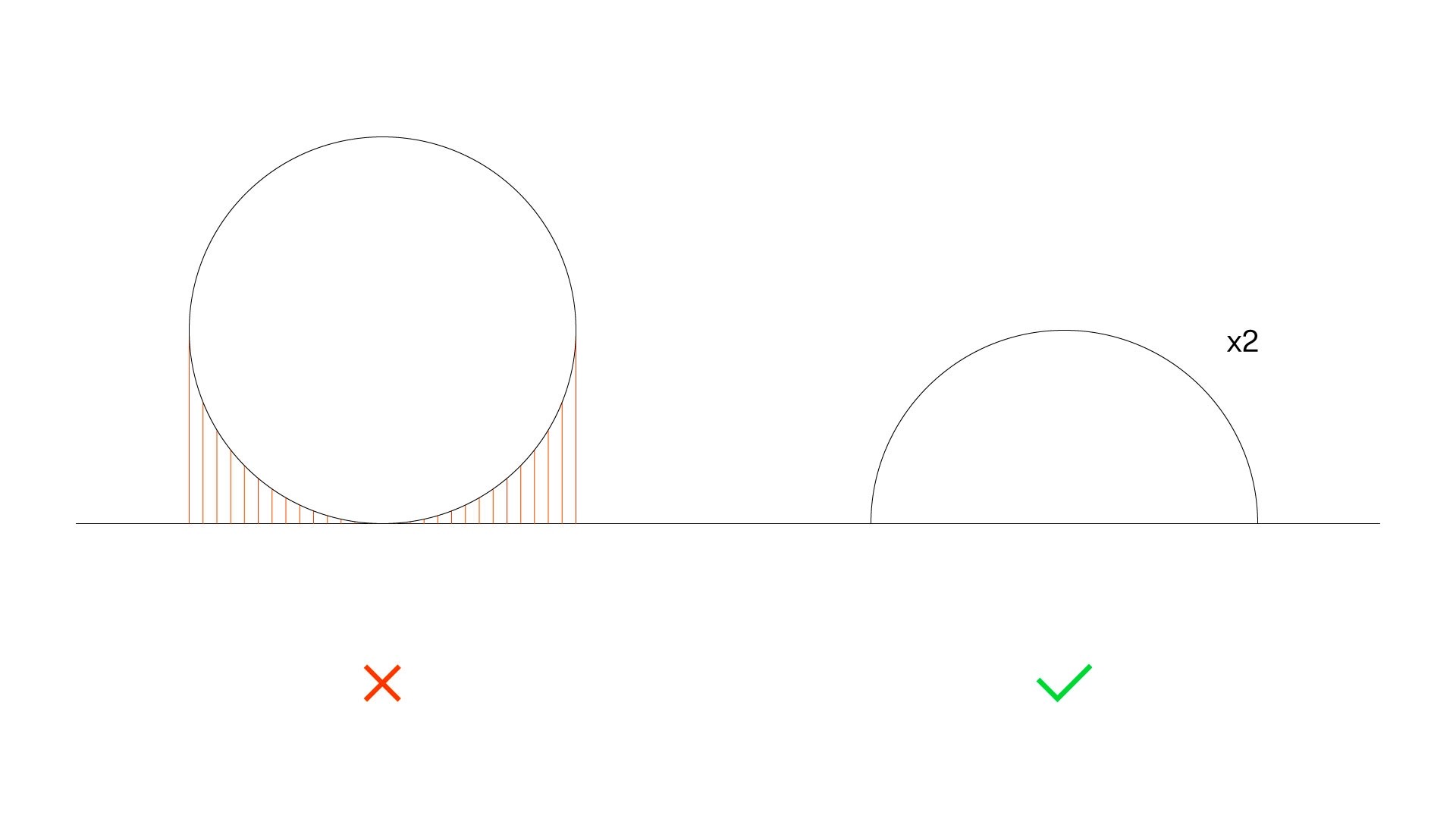
Even though horizontal holes are also undersized, the cause for it is different. When you design a part that has horizontal holes or arches, the top part of the circle becomes an overhang.
If the holes and arches have a visual purpose, then using support material is the best option. However, if the holes are functional and you're going to insert fasteners, you may consider modifying the design to transform it into a teardrop-shaped hole. This will change the overhang and giving you more option to control undersizing.
Part orientation
In most cases, the position in which the part is 3D print won't match the use position. For example, with the word THEY we can see that only the letter Y can be easily 3D printed in its original position.
The goal when orienting a part is to reduce overhangs, bridges and any other elements that may reduce print quality or success rate.
Bottom part surface
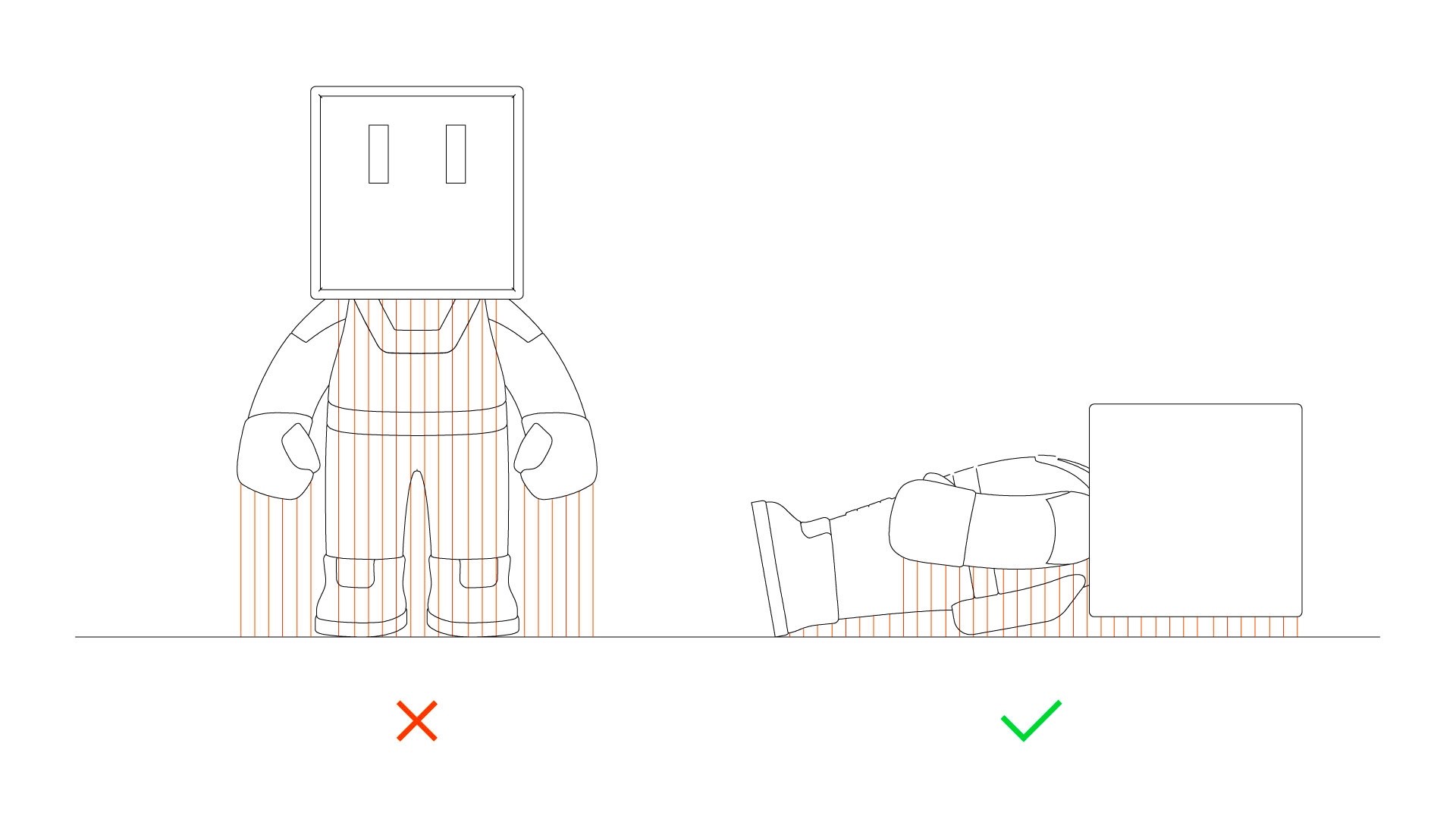
The first layer of the object is 3D printed over a flat surface, and it needs to stick to it very well. FDM 3D printers usually come with a heated bed and specific print surfaces that increase part adhesion. However, you can also design parts with enhanced printability.
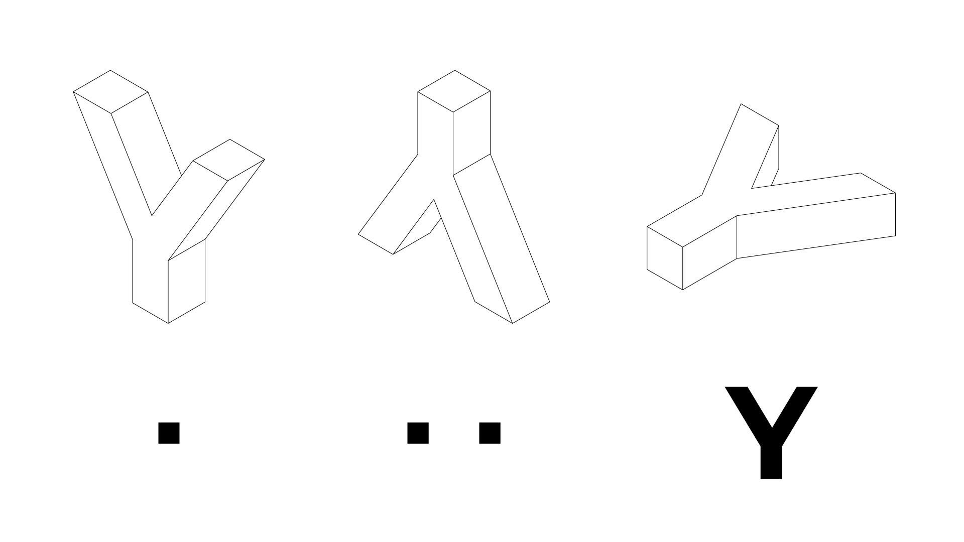
If your design can be printed in multiple ways, find the part orientation that covers the largest surface. For example, if the letter Y is 3D printed in its original position, the first layer will consist of a small square. If you turn the Y upside down, the print surface will double. However, if the model is rotated 90º and it lays flat, the print surface will enormously increase, reducing risks and increasing the print quality.
Use orientation
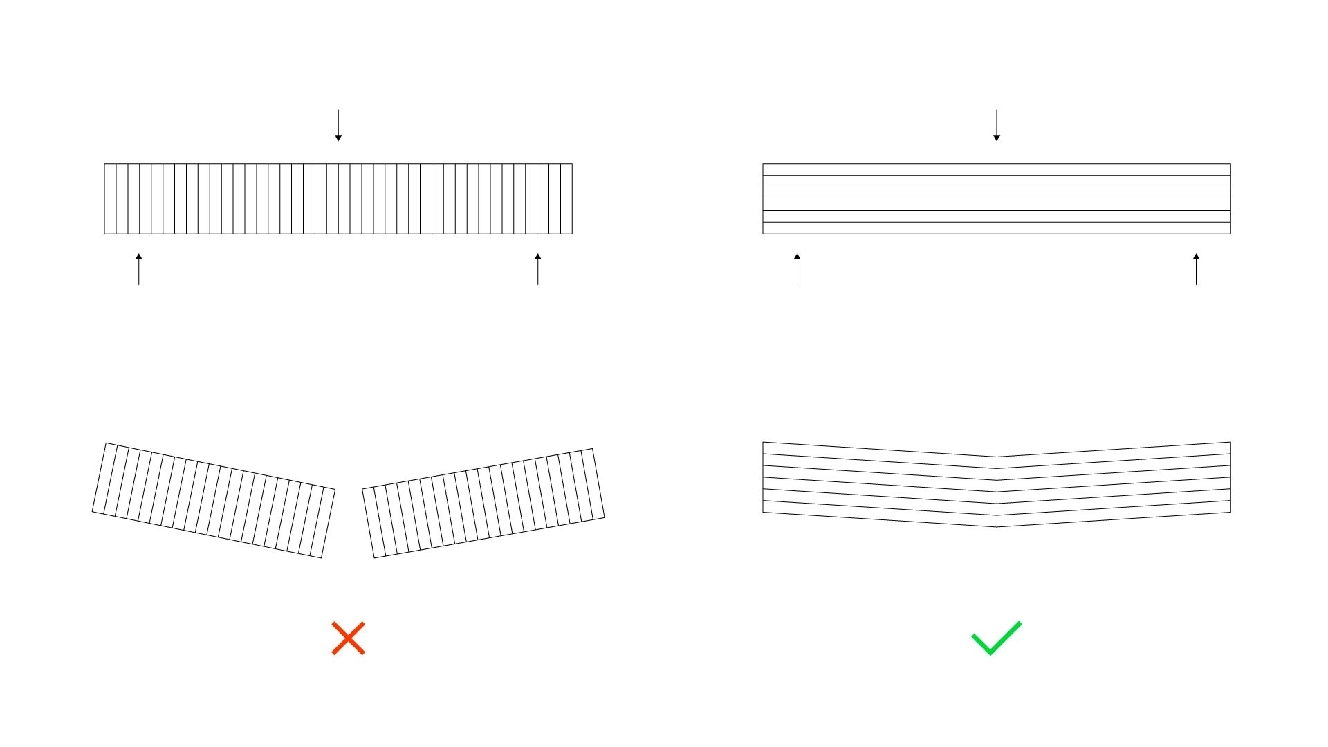
Due to the manufacturing process, 3D printed parts are usually weaker in the direction perpendicular to the layers. This is related to how well the layers stick to each other, and print settings and materials should be taken into account.
If you're printing a functional part, you need to consider the part orientation when preparing the files. The larger the surface of a layer is, the stronger. For example, if you design a long part that needs to resist weight, print it in a way so that the layer lines are perpendicular to the weight direction.
Elephant foot
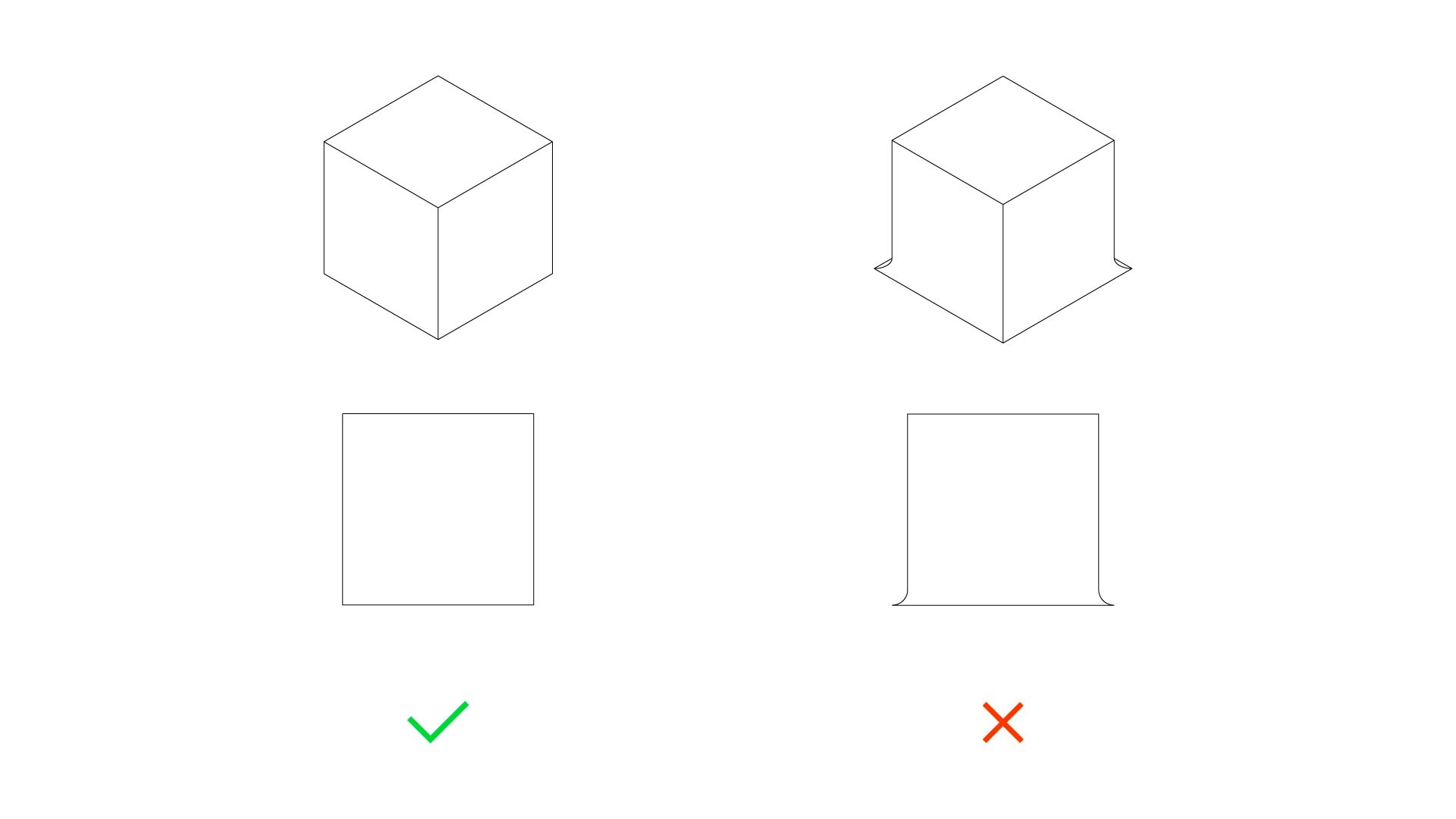
As we've mentioned, good adhesion of the first layer to the print surface is essential. However, sometimes you will end up with a part that has a bulging first layer which is called elephant foot.
This issue is usually the result of poor bed levelling or print settings. When the material is extruded, the nozzle where it flows is too close to the print surface, expanding the material to the sides. Once the first layers are deposited, this issue disappears.
Elephant foot can ruin a part visually and also functionally, as it reduces the tolerances and makes it impossible to combine it with other components that require high precision.
The most common solutions include checking the surface levelling to make sure the nozzle is not too close, printing using a raft, decreasing the bed temperature (especially useful if printing with PLA) or adding chamfers to the bottom edges.
Warping
If elephant foot is a sign of too much adhesion, warping represents the opposite. When you print large objects, bed adhesion tends to be difficult and bed levelling and settings really become essential. You will notice that a part has warped when the corners of the bottom part of your model bend upwards.
Some design solutions that reduce warping include adding rounded corners or simply avoiding large flat models.
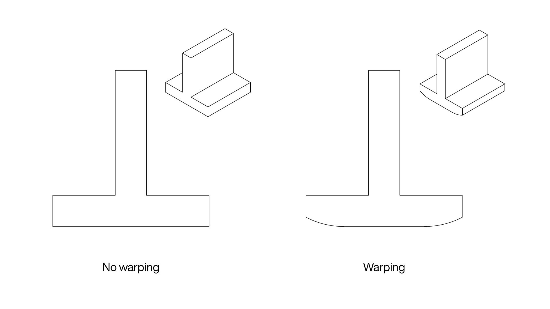
It's also important to mention that bottom edges shouldn't include fillets as it increases warping. On the other hand, small chamfers on those edges can be really useful, as they compensate for elephant foot and allow you to reduce the distance between the extruder and the print surface.
Text size
Adding text to a 3D model can be tricky as not all fonts and sizes will be readable. The 3D printer mechanical features also play an important role as small text usually pushes the print resolution to the limit. Here are some tips if you want to add text to your 3D model:
- Use sans serif fonts such as Arial, Montserrat or Helvetica as the strokes have a consistent thickness.
- Resize the text so that all strokes have a stroke thickness of at least 0.8mm or the minimum wall thickness.
- You can emboss or engrave the text, but the recommended depth is the same: 0.4mm or the nozzle diameter.
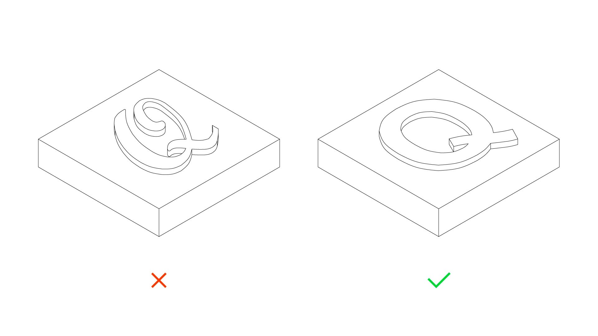
Remember that it isn't about the size of the text, but about the stroke thickness. You can add very small text using a bold sans serif font, but you will need larger text if you want to use a script font.
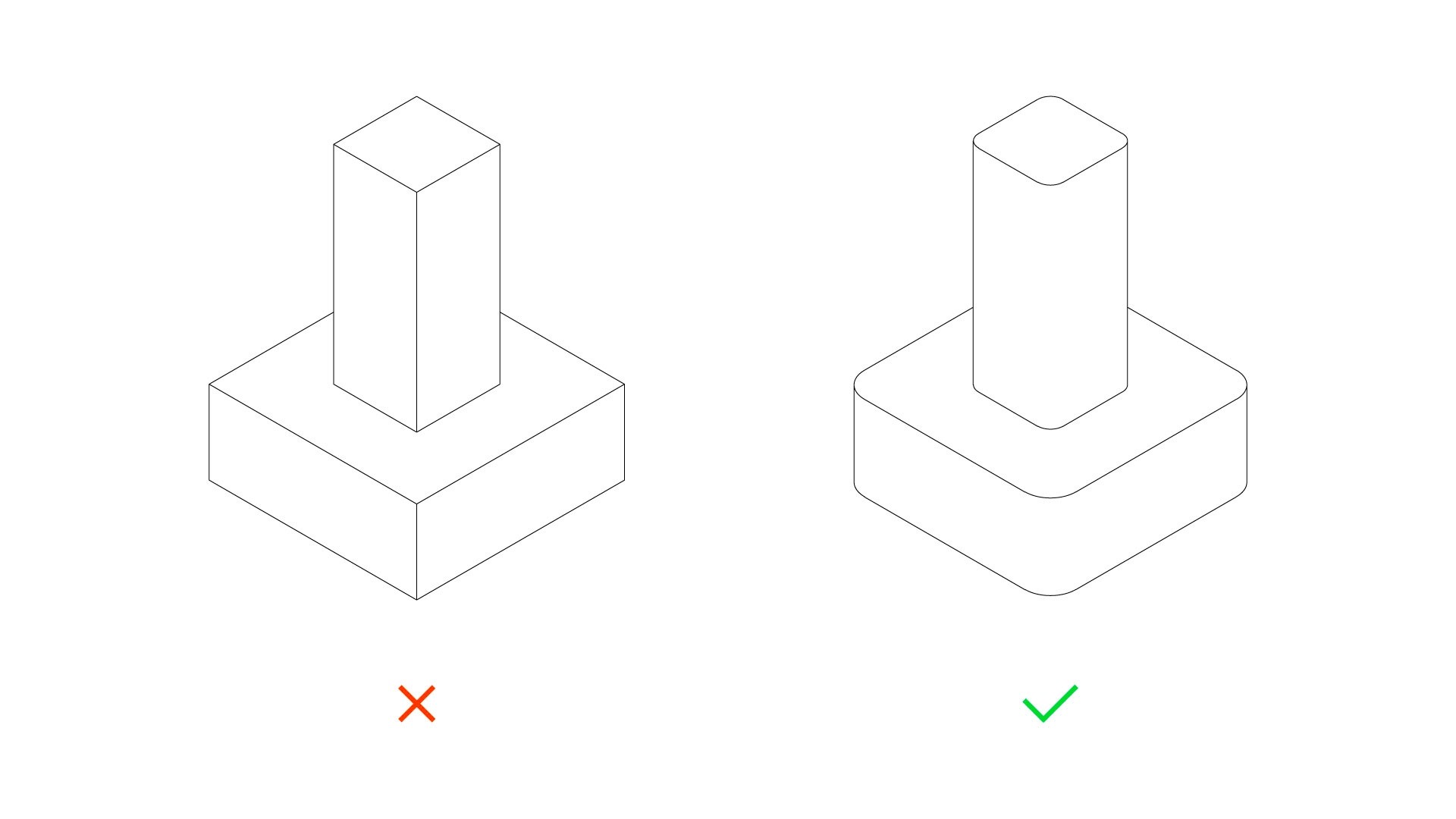
Edges
If you look around you, you will notice that there aren't many objects with sharp edges, being the main reason that it isn't comfortable to hold a sharp object in your hand. Thankfully, it's recommended to round the corners of your 3D model if you're going to use an FDM 3D printer.
The reason behind is not ergonomics, but inertia. The part of the printer that holds the extruder and moves needs to change its direction many times every minute. If it needs to suddenly turn 90º, it will generate a lot of inertia, which will create artefacts on the surface of the model. However, if you round the corners, the inertia will be reduced and the surface of the model will look cleaner. A small 2mm fillet can make a big difference.
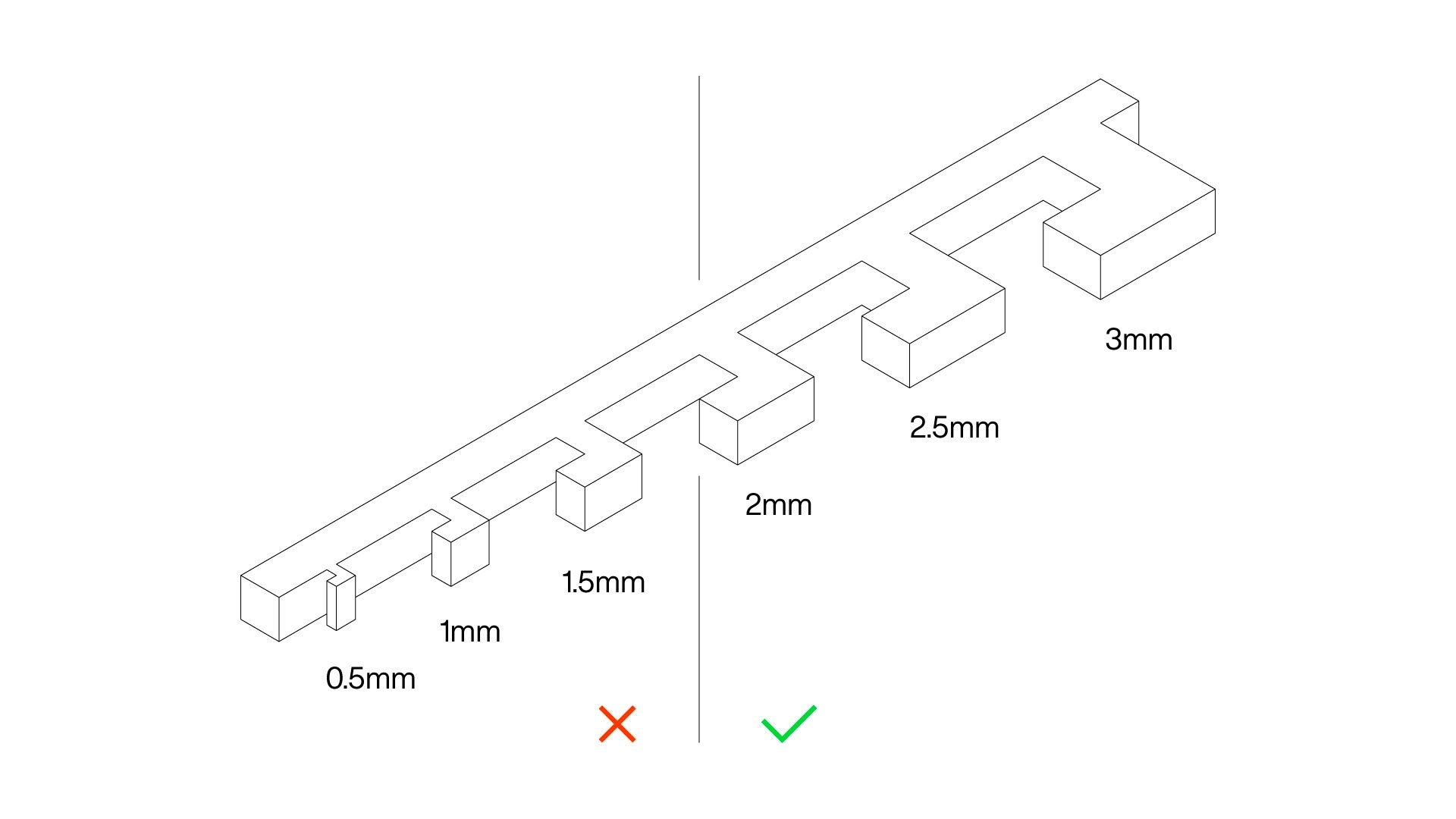
Minimum feature size
The smallest printable feature of a 3D model is determined by the nozzle diameter and the motors the 3D printer uses. Due to the manufacturing process, the extruded plastic needs to be shaped into a shape big enough so that the plastic can solidify keeping the original shape.
The minimum feature size for FDM 3D printing is 2mm, although the 3D model's shape and chosen material may demand slightly larger feature sizes.
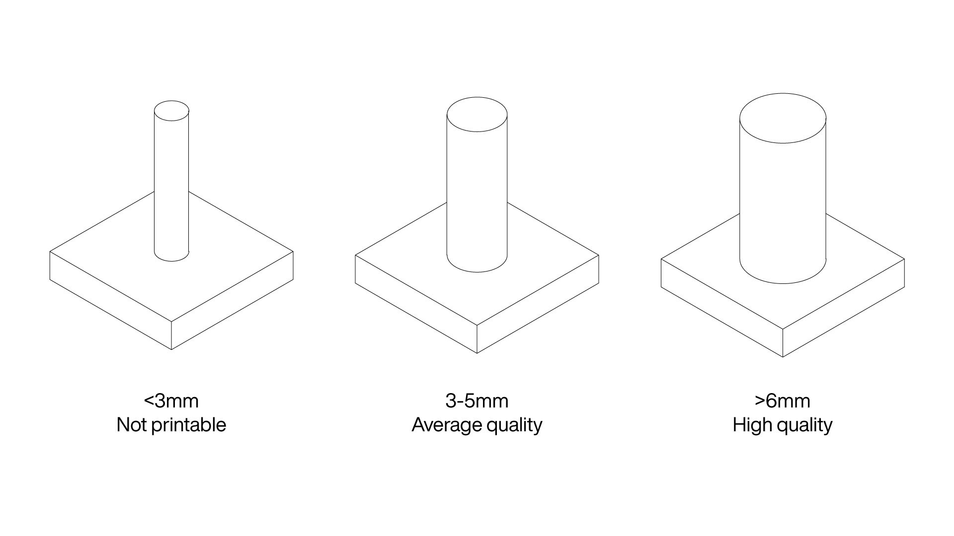
Within small features, vertical pins can be the trickiest ones. Due to the small print surface and the fact that they're usually on the top part of the 3D model, they require a minimum size to print with decent quality.
Vertical pins with a diameter under 3mm will probably deform when printed as the material is extruded faster than it can cool down and solidify. Pins with diameters between 3mm and 5mm are big enough to print, but quality depends on the material and print settings. If possible, use 6mm or larger pins to get the best quality.
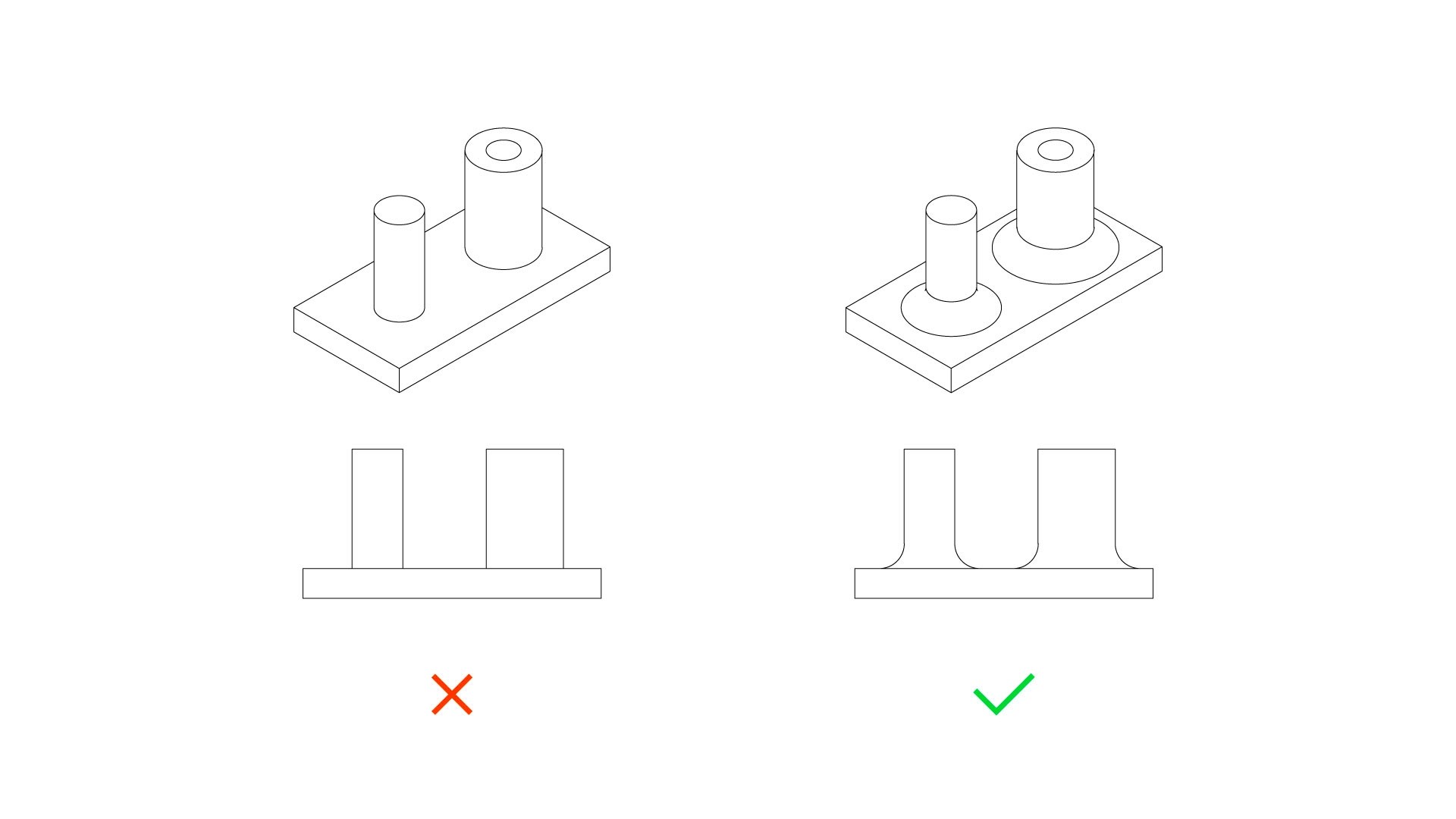
Fillets
If you want to strengthen parts of your 3D model, fillets are the easiest solution. This is especially useful for those fragile elements that connect to the main body. Adding a simple fillet can strengthen the part and reduce stress concentrations.
Rounded edges are essential when designing enclosures as a certain strength must be achieved while having limited space and material.
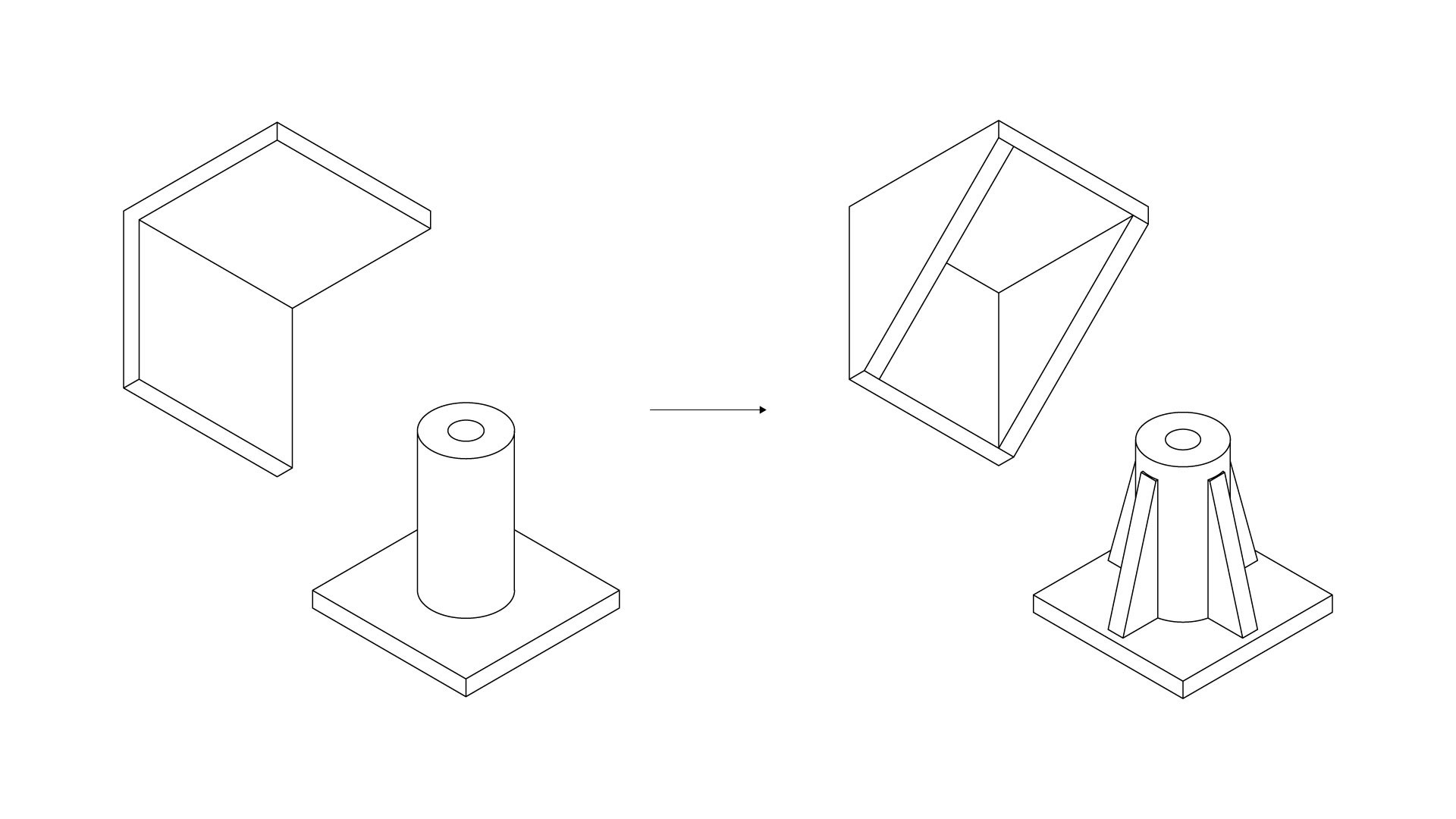
Ribs
If you disassemble an electronic product, it's probable you will find ribs connecting critical design elements in the interior. There is a reason for it. Ribs are used to strengthen thin walls and to hold overhangs. They can be combined with fillets if additional strength is needed and they're compatible with other manufacturing technologies such as injection moulding.
Split the model
If your 3D model is too complex and there is no way to print it in an efficient way, split it up. This will reduce risks as printing smaller parts is generally easier than printing one large part. Also, it will give you the chance to optimise part orientation and increase the overall strength.
Splitting a 3D model is especially useful when you're working with organic or round shapes where there aren't flat bottom surfaces. For example, 3D printing a sphere as one part would require support material and the bottom half would have a low surface quality. However, if you split the model into two halves, they can be printed at high quality without support material.
Interlocking part tolerances
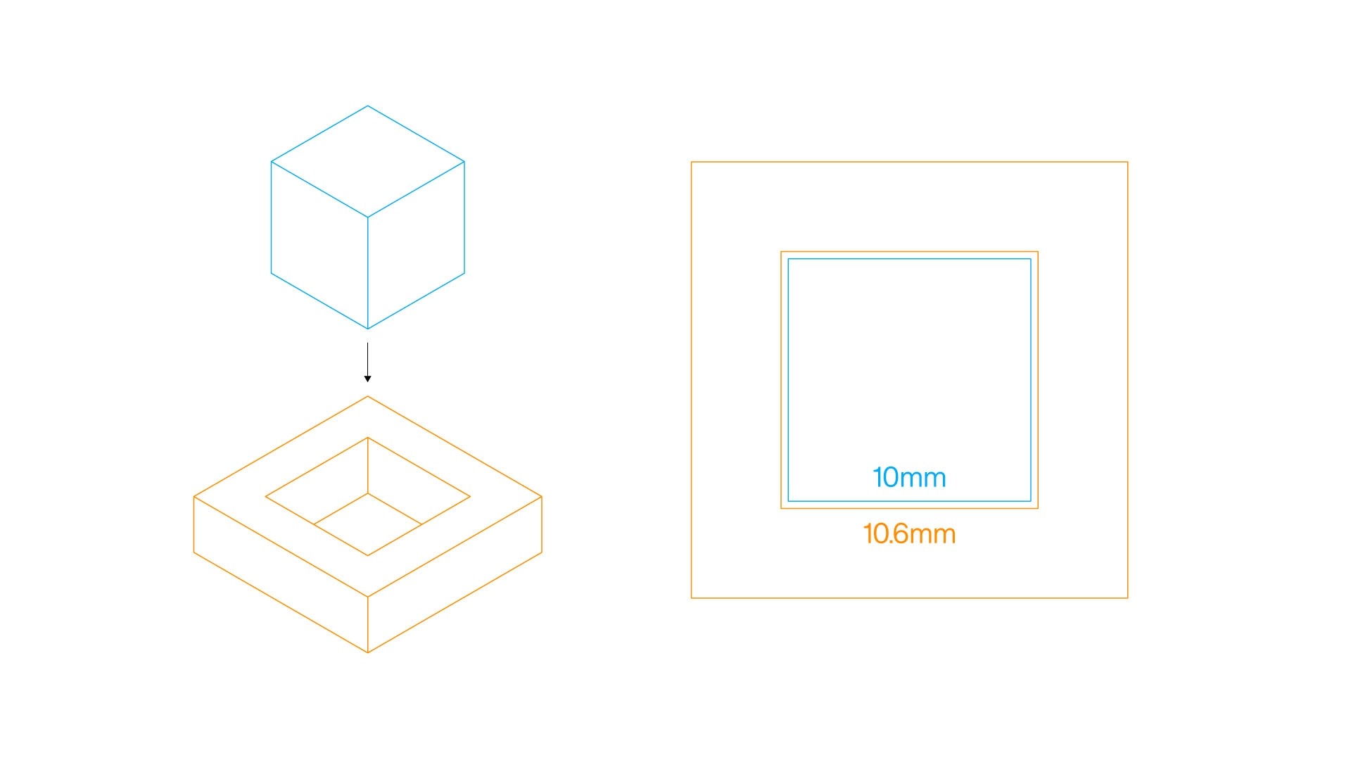
Does your 3D model include two interlocking parts? If it's the case, you should leave a distance of 0.3mm between parts for easy assembly. The recommended clearance depends on the type of 3D printer and how well calibrated it is, although a 0.3mm distance is considered safe enough.
For example, if you want to insert a 10mm cube into a square hole, the hole's side should measure at least 10.6mm (+0.3mm on each side). We recommend testing the machine and contacting the 3D printer manufacturer to know the exact tolerances the machine can achieve. Also, consider the overall dimensional accuracy of the part you're going to 3D print. For example, desktop FDM 3D printers usually offer a +/-0.2mm dimensional accuracy. In FDM 3D printing, it's usually related to the material shrinkage.
Control support material
You can avoid support material in many ways, but sometimes you will need to use it. In those cases, you should be able to control the design in order to add as little support as possible, and in places where it can be easily removed.
It's important to remember that removing the support material can leave marks on the surface, which means you will need to post-process the part if you want a smooth surface finish.
For example, if your model has organic shapes such as branches or arm, it's recommended to orient the model in a way that allows you to place the support material in parts that are not visible or easily post processed.
Even though it's not common, you can always embed support structures within the design as you can control them better than with the slicing software. However, it may not be the best solution if the design is 3D printed with different machines, as each one of them handles support structures in a different way.
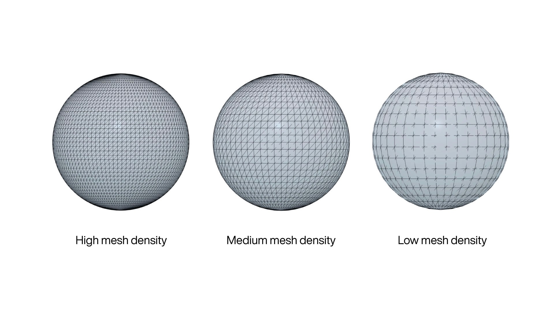
Mesh density
As we mentioned in our article on how to prepare your design for 3D printing, if your design wasn't meant to be 3D printed, you will need to check some details, including the mesh density (also known as mesh resolution).
When you export a 3D model, a mesh is generated. You need to find the right mesh density based on the object's purpose. A low-density mesh will generate a 3D printed object where you can see the faces, which isn't ideal if it's a visual element. On the other side, if the mesh density is too high, the 3D printer and the slicing software may have issues handling the file.
Material
There are dozens of 3D printing materials, and each one of them has its own design requirements. This means that the design you 3D printed with strong PETG material may not print with the same quality if you use flexible materials.
Each material manufacturer has their own recommendations, and you need to take them into account when you design. Some critical aspects that should be considered include overhang angle, bottom layer adhesion and minimum feature size.
Conclusion
Most of the things mentioned above can be easily implemented in most modeling workflows. Many small details improve the 3D printing experience when implemented.
It is imperative for both 3D printing consumers and manufacturers to understand how 3D printing works and how to design for it. 3D printing has changed how we design and manufacture because we can adjust and modify almost any parameter to make unique products.
We hope this article provides a useful guide to prototype and making better products. Please let us know your best prototyping tips in the comment thread below. And if you found this article helpful, help others by liking and sharing it.

Get the latest articles on your inbox